
West Port Middle East specializes in engineering and supplying cable management solutions that meet the precise requirements of electrical contracting projects across the GCC. Unigroup offers a line-up of high-performance cable trays, Trunking and Channel Systems for all your cable routing requirements. Our cable tray systems are engineered for modern infrastructure, ensuring safe, organized, and efficient cable routing across commercial, industrial, and utility. Cable Trays are support systems used in building electrical wiring. These cable support systems are commonly used to support insulated power and communication cables. Cable trays provide a more preferable alternative to electrical conduit systems and open wiring. Cable tray systems are generally. Premium Construction: Made from galvanized steel, stainless steel, or aluminum, these trays resist corrosion and provide high load-bearing capacity in harsh conditions. From residential towers to industrial plants, our extensive portfolio of products and accessories is designed to provide. A form of cable management system used for supporting and arranging electrical cables and wires in commercial, industrial, and residential structures is known as GI Cable Tray, also known as Galvanized Iron Cable Tray.
[PDF]
Because fiber optic cables don't come in one continuous length, sections must be joined together through splicing. This process fuses two glass strands so light signals can travel through them without interruption. Below is a detailed look at each step of fiber optic network construction, including key terms and methods used across the industry. Engineers and. We are experts in the installation and use of fiber optic cable to residences, apartment buildings, businesses and cell sites. We complete complex construction projects consisting of aerial and underground deployments in varied, often difficult, working environments. Our services include everything. The Fiber Optic Association, Inc. (FOA) was founded in 1995 to help develop the workforce to build the fiber optic networks to support a rapid expansion in communications and the Internet. Delivers state-of-the-art fiber optics solutions by developing high-tech equipment and subcontractor expertise. Utilizes state-of-the-art technologies to splice a wide variety of different. This recommended practices document is a comprehensive manual for optical fiber construction and testing. Sections are included for project management; cable handling, testing and equipment; overhead cable placement; underground cable placement; underground enclosures; bonding and grounding; cable. 4. FO-VC2 JOINT USE - VERICAL MIDSPAN CLEARANCES 48. FO-GB GROUNDING AND BONDING 49.
[PDF]

This section provides an overview for busbars as well as their applications and principles. Here are the top-ranked busbar companies as of May, 2026: 1. Chatsworth. Busbars also known as bus bars, barra electrica, or busbar electrical systems are essential components in modern electrical distribution. Whether used in industrial bus bars, EV charging, renewable energy plants, or building infrastructure, busbars offer compact, efficient, and safe current. High Voltage Busbars are critical components in electrical power systems, designed to conduct high voltage electrical currents efficiently and safely. They are used in substations, switchgear assemblies, and electrical distribution systems to connect different parts of the system and manage the. According to Mordor Intelligence, the busbar market was valued at USD 5. 3 billion in 2023 and is projected to reach USD 7. 5% during the forecast period. What. The global busbar market will expand at a great rate and reach USD 19. 24% between 2023 and 2033. The top companies in busbar market are Siemens AG, Connectivity, Mersen, Schneider Electric, Rogers Corporation, Legrand.
[PDF]

Poland's high voltage oil insulated switchgear market is estimated at USD 145–175 million in 2026, with a compound annual growth rate of 3. 5% through 2035, driven primarily by grid modernization and renewable energy integration. Successful go‑live of day-ahead and intraday capacit. informs that under the Single Day-Ahead Marke. Due to changes in information requirements for the electricity market and Polish Power System Operation a new website containing system data has been launched. Transmission substations account for approximately 55–60% of. The electricity transmission network in Poland is managed by Polskie Sieci Elektroenergetyczne SA (PSE), which is the sole transmission system operator (TSO) in the country. The entire power system in Poland and throughout Europe (excluding the frequency of railway electric traction in Germany and. The ANIA Electrical Centre, operating within the structure of ANIA HOLDING, has been providing comprehensive solutions for the distribution of electrical goods for over 30 years. PSE is the owner of Poland's high voltage electricity grid and is responsible for grid. Polenergia Dystrybucja builds and maintains its own power infrastructure across Poland, through which it distributes and sells electricity. Your browser does not support the video tag. Our clients include shopping malls, office buildings, industrial parks, warehouse centers, housing cooperatives.
[PDF]

Splice Diagrams or Matrices capture an electric or optical network inside a location – documenting cables, ported equipment, and connections. Splices are fiber-to-fiber, port-to-fiber and port-to-port. Fiber optic cable splicing involves joining two fiber optic cables together. Another method of connecting optical fibers is termination or connectorization, which consists of processing the end of a fiber optic bundle so that it can be connected to other fibers or devices through fiber optic. In this guide, we cover the basics of fiber optic splicing, how to perform splicing using two different methods, and finally some best practices to perform good fiber splicing. Ensure Your Splicing Tools are Clean – #2. Use and Maintain Your. What to show on a network diagram? Fiber optic network diagrams represent the architecture and connectivity of fiber optic systems, and their design philosophy integrates technical, functional, and conceptual aspects. The diagrams abstract complex details of fiber optic systems to make them. This Geoschematics drawing remains easy to read despite containing more than 2000 fibers and 500 splices. All students and instructors must wear safety glasses in this lab. It is copyrighted by the FOA and may not be distributed without FOA permission. This VHO covers similar material to the videos on YouTube. The lab manual has several.
[PDF]

In this guide, you will find a chronological description of the fusion splicing process, the principal technical standards, and answers to the real-life questions network engineers and procurement teams may have. 📦 For purchasing, use the RP Photonics Buyer's Guide for fusion splicers. It provides an expert-curated supplier directory, buyer-focused technical background information, and structured selection criteria to support professional procurement decisions. This article explains the principle of fusion. Fusion splicers play a crucial role in the field of optical fibre communications by enabling the permanent bonding of two strands of glass fibre to create a continuous pathway for light to travel through. This process is achieved through precise alignment and fusion of the fibre ends using an. Fusion splicing is the process of fusing or welding two fibers together usually by an electric arc. Fusion splicing is the most widely used method of splicing as it provides for the lowest loss and least reflectance, as well as providing the strongest and most reliable joint between two fibers. Each splicer is equipped with a cleaver and stripper, conveniently includes in a single case. The goal is to align the microscopic glass cores (typically.
[PDF]

Compare fiber optic and copper Ethernet cables across speed, distance, cost, installation difficulty, and use case metrics. Use the interactive scenario selector to find the right medium for your specific network — all processed locally in your browser. PoE Required?. The core difference between fiber optic and copper cables lies in how they carry data. One uses light, the other electricity—and that distinction shapes everything from speed to signal integrity. Fiber optics transmit data as pulses of light through ultra-thin strands of glass or silica. Both technologies can deliver high-speed connectivity, but they behave differently under real-world constraints such as. However, the exponential growth in data demand has positioned fiber optic technology as the superior alternative for performance, scalability, and future-readiness. This article provides a detailed technical comparison between fiber optic and copper cables, offering a clear perspective for. Fiber optic tends to be the more premium solution, while copper wiring is far more common, but why is that? What are the differences between these two cable types, and why might you want to pick one over the other? Here's everything you need to know about fiber vs. copper cables, to help you pick. Several factors are converging to drive the switch from copper to fiber – and cost is a big one. A recent investor presentation by AT&T claimed that fiber was 35% less costly to maintain than copper.
[PDF]

For busbar sizing, the primary references are IEC 61439 (for low-voltage switchgear and controlgear assemblies) and IEC 60287 (for current-carrying capacity of cables). IEC 61439 is a standard developed by the International Electrotechnical Commission (IEC) that covers design verification for low-voltage electrical products and assemblies. The IEC 61439. With SIRIUS, SENTRON, SIVACON and ALPHA, we offer an innovative portfolio for standard-compliant and demand-oriented applications. Efficient engineering tools and innovative cloud-based solutions can be flexibly tailored to individual requirements. com/system-certificates/ep). The. 7 cycles of 24 h each to salt mist test according to IEC 60068-2-11; (Test Ka: Salt mist), at a temperature of (35 ± 2) °C. The test shall be carried out according to IEC 60068-2-2 Test Bb, at a temperature of 70 °C, with natural air circulation, for a duration of 168 h (7 days) and with a recovery. The International Electrotechnical Commission (IEC) issues globally accepted standards that promote safety and efficiency in electrical engineering. Standard sizes and ratings and a complete line of components allow each system to be tailored to suit the requirements of each application, while at the same time provide the.
[PDF]
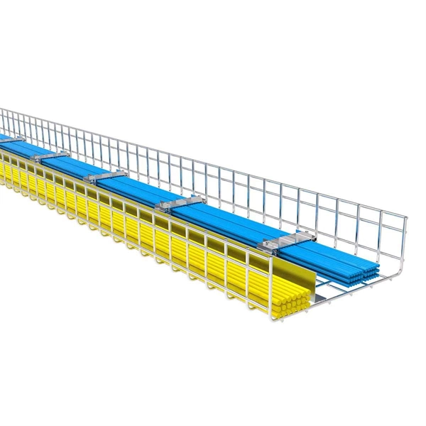
Standard splice plates can often provide a safe electrical path if they are UL Classified and bolted tight. However, you must use copper bonding jumpers if the tray is painted or has expansion joints for movement. A. The intent of this article is to review grounding practices for cable tray wiring systems. The Equipment Grounding Conductor is the electrical circuit's safety conductor. When designing a cable tray. Snap Track requires only single bonding jumper. Installation Guideline: Scroll to bottom of page to view All Bonding Jumpers Cut Sheets A bonding jumper is required to be installed with adjustable splices and expansion splices. If an EGC cable is installed in or on a cable tray, it should be bonded to each or alternate cable tray sections via grounding clamps (this is not required by the NEC® but it is a desirable practice). In addition to providing an. Do I have to use a bonding jumper at each cable tray splice point that is bolted tightly together? I currently have 3 runs of 24 tray about 80ft long. we have one expansion plate section per run in which I plan on using a bonding jumper at, I am curious about all other points You aren't even. Wire mesh cable trays are widely used in commercial offices, industrial facilities, data centers, and smart building infrastructure because they provide unmatched flexibility, excellent airflow, and fast, adaptable installation. Their open-grid design makes it easy to route, add, or modify cabling.
[PDF]

The Israeli cable trays market is a critical component of the nation's industrial and construction infrastructure, serving as the backbone for organized and secure cable management across diverse sectors. As of the 2026 analysis, the market is characterized by steady demand driven by sustained. A cable tray is an organized support structure designed to secure and route these insulated electrical cables. It acts as a dedicated pathway for power distribution and data transmission, often supporting cables hidden behind walls or above ceilings. People use them in many buildings and work places to give cables a steady place to run. Cable trays come in different types: Materials: They can be metal (like steel with a coating, or stainless steel), plastic (like. In the electrical wiring of buildings, a cable tray system is used to support insulated electrical cables used for power distribution, control, and communication. When properly selected and installed, cable trays simplify routing, improve accessibility, and support future expansion while. Metal cable trays are widely used in demanding industrial settings to support, organize, and protect extensive cabling systems, ensuring efficient and safe power and data distribution. Their robustness and adaptability make them essential in sectors where conditions can be extreme, compliance with.
[PDF]
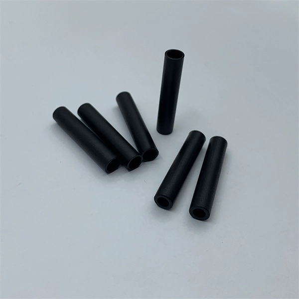
Optical Fiber Cable & Accessories Price in Nepal, Kathmandu. Buy with best and reasonable price @ ITShop Nepal. Nepal - Shop for Best Online at Daraz. np Wide Variety of fiber optic box. Great Prices, Even Better Service. Made of brand new materials, sturdy and durable, resistant to impact, corrosion, sealed and waterproof, safe and worry free Engineered for outdoor use, this junction box showcases a robust waterproof design, safeguarding critical fiber optic connections against harsh weather and ensuring reliable. Optical Fiber Cable & Accessories Price in Nepal, Kathmandu. SÜRGÜLÜ PATCHPANEL SC UPC DUBLEX 24XADAPTÖR 48XPIGTAIL RAL7035 1u 19” MEK. GJS-901-2 fiber optic splice closures (FOSC) are used to distribute, splice, and store the outdoor optical cables which enter and exit from the ends of the closure. There are two connection ways: direct connection and splitting connection. Applicable to situations such as overhead, man-well of. vianet: Vianet Communication Ltd. is a leading Internet & TV service provider in Nepal. Since 24 years, Vianet Communication has always remained at the forefront, providing reliable and affordable Fiber Broadband Internet Services.
[PDF]

GYTA is an outdoor stranded loose tube fiber optic cable with aluminum tape armor (indicated by the “A” in GYTA). It is designed for aerial and duct installations but is not recommended for direct burial. It provides an excellent balance of moisture protection and mechanical flexibility, making it the preferred choice for duct and aerial backbone networks. Perfect for long-distance communication. We manufacture high quality products according to European and US standards. The aluminum. Outdoor Duct Optical Cables are strands of specially designed fiber optic cable that are ideally suitable for deployment in underground conduits or ducts. This type of cable guarantees total security for optical fibers while providing long-distance, high-speed data transmission. We supply GYTA fiber optic cable from 2 fiber cores to 288 fiber cores. Both single mode type and multimode types are available. precise control for fiber excess. GYTA fiber optic cable is an outdoor loose tube cable that uses aluminum tape armor for additional mechanical protection. This cable design is commonly installed inside underground ducts or conduits where fiber cables require protection from external pressure and environmental conditions. It is known for its high tensile strength, high flexibility, and excellent transmission performance. In this article, we will discuss the characteristics of the GYTA optical cable.
[PDF]

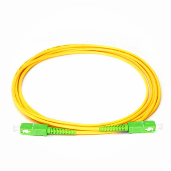
This video goes over common types of connectors, their respective adapters, and how to properly connect and disconnect them. more Are you interested in seeing how fiber optic connectors get. Unplugging a fiber jack, also known as a fiber optic connector, is a delicate process that requires attention to detail and proper handling to ensure the integrity of the fiber optic cables and connectors. Fiber optics are used in a variety of applications, including telecommunications, internet. If you're wondering how to remove fiber optic cable from connectors, there are a few different ways to do it. You need to know which connector is the correct one for the cable and what kind of wire it's made of. You can also use shears or wire cutters to cut through the connector. This article. Fiber optic connectors are essential components in fiber optic networks, providing a reliable connection between cables and equipment. Removing these connectors requires care to avoid damaging the delicate fibers or the connector itself. To connect a fiber optic cable to SFP optical module, first ensure the SFP is fully inserted into the network port until it "clicks", then remove the dust caps from both the SFP and the LC fiber optic connector.
[PDF]