
Mount individual circuit breakers in the designated positions within the distribution box. Each breaker should match the current rating and type required for its specific circuit. Ensure proper connection to the busbars and secure mounting to prevent loosening over time. Correct wiring methods for circuit breakers within distribution boxes are fundamental to ensuring electrical safety and compliance with established codes. The distinction between 1P and 2P circuit breakers plays a pivotal role in determining the appropriate protection level for various circuits. This guide shows you how to organize circuit breaker wiring properly. You will learn to build a safe, efficient, and professional electrical system today. Circuit breaker wiring configurations involve organizing main switches, busbars. Circuit breakers, as important components in distribution boxes, can protect circuits from the effect of overload and short circuits. It serves as a central hub for distributing electricity throughout a building, ensuring that power is delivered safely and efficiently to all the required locations. We'll also look at whether it's good enough for your home, and what to do if your panel needs an upgrade. We want to help keep your home powered safely and. A breaker box, also known as a circuit breaker panel, is an essential component of any electrical system. To understand how a breaker box works, it is helpful to.
[PDF]

The circuit diagram of the protective relay is made up of current transformer primary windings, current transformer secondary windings, relay operating coils, circuit breakers, and the tripping circuit. The relays are in round glass cases. The rectangular devices are test connection blocks, used for testing and isolation of instrument transformer circuits. In electrical engineering, a protective relay is a relay device designed to trip a circuit breaker when a fault is detected. : 4 The first. The working of a protective relay is based on continuous monitoring of electrical quantities such as current, voltage, frequency, and power. A typical protective relay circuit is shown below: Protective Relay Circuit Diagram The first part of the circuit consists of the primary winding of a CT. A relay is a four-terminal electrical switch, used to control any electrical circuit with an independent low-power signal and also to control various electrical circuits with a single signal. The terminals of the relay mainly include; common, coil, NO (normally open) & NC (normally closed). It functions as a watchdog by constantly surveying multiple system components including voltage, current, frequency, and phase angle. During a fault condition, there is a change. Protective relays and devices have been developed over 100 years ago to provide “lastline”of defense for the electrical systems.
[PDF]

When a circuit breaker keeps tripping, the cause usually falls into one of three categories: overloads, short circuits, or ground faults. The key is knowing what's driving each one so you can troubleshoot it correctly. This comprehensive guide, compiled by ELECO's technical support team based on decades of global field experience, provides a clear, actionable roadmap to identify and solve the five most common causes of frequent tripping, saving you time and ensuring compliance on any international project. The bottom line: A tripping breaker means your electrical system is doing exactly what it's supposed to do. Now we need to figure out why. Understanding which one you're dealing with helps you know if this is something you can handle or if you need. Circuit breakers serve as your home's electrical guardians – they automatically cut power when detecting dangerous conditions. Occasional tripping is normal protection behavior, but frequent tripping signals underlying issues needing attention. It's a typical issue. Below, you'll find reasons why this occurs and tips to avoid it moving forward. Get a handle on your circuit breaker problems! Circuit breakers are protection.
[PDF]

When it comes to testing fiber optic cables, a Visual Fault Locator (VFL) is an essential tool in your toolkit. A VFL is used to detect faults, breaks, or bends in fiber optic cables by emitting a bright red light that is visible even through the fiber's jacket. Let's dive into everything you need to know about mastering VFLs. It's a cost-effective and. Visual Fault Locator (VFL) testing is one of the most fundamental inspection methods used in FTTH, ODN, and data center environments. A VFL emits a visible red laser (typically 650 nm) that travels along the fiber core and leaks out at points of excessive loss, fiber breaks, or microbends. Although. The Fiber Visual Fault Locator Kit is an essential tool for network technicians and engineers; it provides an accurate and quick method of finding such problems as breaks, bends or faults that may affect the network's operation. It works by injecting a visible red laser light (usually in the 650nm wavelength) into the fiber. When the light encounters a fault, such as a break, bend, or bad splice, it leaks out of the fiber, making the. Conducting efficient, repeatable fiber optic cable certification requires an array of specialized test equipment: Optical Loss Test Set (OLTS) – Integrates adjustable light source and power meter for efficient, Tier-1 insertion loss testing. Visual Fault Locators – Handheld devices projecting.
[PDF]
The VFL 30mW 30km tester meter is a powerful and versatile instrument capable of tracing and identifying fiber optic cable faults within a range of 30 kilometers. It employs a 30mW VFL light source, which is more than sufficient for long-distance fiber optic testing applications. This QuickTreX ® high quality visual fault locator (VFL) laser test pen is compact, rugged, and perfect for locating bends and breaks in jacketed or bare fiber within 30Km. It's also great for identifying specific connectors in patch panels. This VFL emits red light by using a 650nm semiconductor. Easy to Check Fiber Faults - This visual fault locator can accurately detect and locate fiber breaks, poor connections, bending, or cracking. The detector will emit a 650nm bright light for fiber tracing, breaks or faults in the fiber will refract the light. PRACTICAL DESIGN AND EXCELLENT FUNCTION –. The Pen Shape Visual Fault Locator (VFL) is a robust, cost-effective fiber optical cable test tool for locating faults within OTDR dead zones. As a visual fault identifier (VFI), it can quickly identify faults in fiber optic jumper cables, distribution frames, patch panels, and splice trays. Using. New: A brand-new, unused, unopened, undamaged item in its original packaging (where packaging is. Packaging should be the same as what is found in a retail store, unless the item was.
[PDF]
This study presents the experimental investigations on heat transfer and airflow in a closed refrigerated display cabinet. Air and product temperatures and air velocity were measured with thermocouples and.
[PDF]

In Q1 2019 NSS Labs performed an independent test of the Oracle Talari SD-WAN E1000 v7. NSS has created three use cases to represent the most common reasons why enterprises deploy software-defined wide area network (SD-WAN) products: Manageability & Cost, Performance, and Security. The troubleshooting tools are now easily accessible from the various monitoring pages of Cisco SD-WAN Manager, such as Site Topology, Devices, Tunnels, and Applications, thereby providing you with context-based troubleshooting guidance. For information on interface bandwidth, see the Interface Summary Report. This report is available in WatchGuard Cloud for Fireboxes that run Fireware v12. To view the report, you must configure. The Monitoring tab is a dashboard that displays a summary widgets of all your SD-WAN device health metrics. This tool provides actionable intelligence about the activity on your SD-WAN network, by allowing you to quickly identify applications or links experiencing performance issues. The ideal. Certifications, manuals, datasheets, and specifications for hundreds of thousands of electronic devices. Jump directly to brand. be attenuated by at least 30 dB relative to the maximum in-band peak PSD level in 100 kHz. Set the RBW = 100 kHz, VBW = 300 kHz, Detector = peak. Set Sweep time = auto couple, Trace mode = max hold. Use the peak marker function to determine the maximum amplitude level.
[PDF]
Home appliances TV sets, VCR, Microwave ovens Office machines Industrial equipment NC machines, Robots, Temperature controllers Photocopiers, Vending machines. Space saving design Wiring can be done with ease (DIN terminal). N.C. contact raw N.O. contact raw COM contact raw Coil terminal raw. N.C. contact raw N.O. contact raw COM contact raw Coil terminal raw. For Cautions for Use, see Relay Technical Information.
[PDF]
Distance relays, also known as impedance relay, differ in principle from other forms of protection in that their performance is not governed by the magnitude of the current or voltage in the protected circuit but rather on the ratio of these two quantities.OverviewIn, a protective relay is a device designed to trip a when a is detected. The first protective relays were electromagnetic devices, relying on coils operating on moving par. Electromechanical protective relays operate by either, or. Unlike switching type electromechanical with fixed and usually ill-defined operating voltage thresholds. Electromechanical relays can be classified into several different types as follows: "Armature"-type relays have a pivoted lever supported on a hinge or knife-edge pivot, which carries a moving contact. These relays may.
[PDF]

RCCBs (Residual Current Circuit Breakers) should be installed in key areas of your home's electrical system for maximum safety. The best place to install an RCCB is in the distribution board (DB box), which controls the electrical circuits throughout your home. This location ensures that the RCCB protects the entire electrical system by monitoring the current flow throughout. For added protection, you can also. A residual-current device (RCD), residual-current circuit breaker (RCCB) or ground fault circuit interrupter (GFCI) is an electrical safety device, more specifically a form of Earth-leakage circuit breaker, that interrupts an electrical circuit when the current passing through line and neutral. The primary function of an RCD is to monitor the electrical current flowing in a circuit and quickly disconnect the power supply if it detects an imbalance current (leakage of current to ground) between the live and neutral conductors. An RCD is essentially a current-operated ELCB and is commonly. RCCB Definition: A Residual Current Circuit Breaker (RCCB) is defined as a safety device that detects and interrupts a circuit when there is a leakage current to the ground. It can swiftly disconnect the circuit when a fault current happens and prevent wiring damage. In this article, we explain what an RCBO is and how it.
[PDF]
High-definition temperature sensing based on the natural Rayleigh backscatter in optical fiber delivers a virtually continuous line of temperature measurements with sub-millimeter spatial resolution. 1. Map temperat.
[PDF]

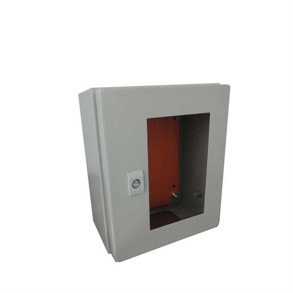
Mount individual circuit breakers in the designated positions within the distribution box. Each breaker should match the current rating and type required for its specific circuit. Ensure proper connection to the busbars and secure mounting to prevent loosening over time. When opening the distribution box, several different brands of circuit breakers are installed inside. It seems that the sizes match and the installation is fine, and this. The feeder amp rating is sized based on the sum of the amp rating of the largest branch protective device plus the full-load currents of the other loads. This value is added to the full load currents of the. Finding the right circuit breaker for your electrical panel is crucial to ensure safety, performance, and code compliance. Not all breakers are interchangeable across different panel brands – each manufacturer designs its breakers and panels as a matched system. Using a breaker that isn't made or. In industrial power distribution systems, cable distribution boxes (also known as power distributor boxes, distribution electrical boxes, or electrical power distribution boxes) are the core hub of power transmission, branching, and protection. You lower the chance of circuits getting too hot or overloaded when you pick the right box for your needs. A single circuit breaker installation mistake can cost your facility thousands in downtime, equipment damage, or worse—put lives at risk.
[PDF]

This guide shows you how to organize circuit breaker wiring properly. You will learn to build a safe, efficient, and professional electrical system today. Circuit breaker wiring configurations involve organizing main switches, busbars, and branch breakers within a distribution box. While some homeowners may attempt this, it's highly recommended to hire a qualified, licensed electrician for circuit breaker box wiring. This is a complex and potentially dangerous task that involves working with high voltage electricity. Mistakes can lead to serious injury, fire, or damage to. A breaker box, also known as a circuit breaker panel, is an essential component of any electrical system. It is responsible for distributing electricity throughout a building, ensuring that each circuit receives the proper amount of power. To understand how a breaker box works, it is helpful to. When installing or troubleshooting a power distribution system, understanding how to correctly connect the main electrical supply to the control panel is crucial. The first step involves running a dedicated cable from the incoming supply to the distribution panel, ensuring it is rated for the load. How to read these diagrams. This page contains wiring diagrams for a service panel breaker box and circuit breakers including: 15amp, 20amp, 30amp, and 50amp as well as a GFCI breaker and an isolated ground circuit. Messy distribution boxes are dangerous and very hard to fix.
[PDF]


