
The IEEE standard for protection relays refers to a collection of guidelines developed by the Institute of Electrical and Electronics Engineers. These standards define the performance, accuracy, reliability, and testing requirements of protective relays used in electrical systems. Relay systems protect high-voltage equipment and transmission lines to ensure safe, stable systems. Although failure of a protective relay system may have severe local or regional impacts, most protective relay systems are not required to operate to prove they are in working order. Many of the protective relay systems are seldom called upon to work and have little means of proving they. The testing and verification of relay protection devices can be divided into four groups: Type tests are needed to prove that a protection relay meets the claimed specification and follows all relevant standards. Since the basic function of a protection relay is to correctly function under abnormal. Protective relays are decision-making elements in the protection scheme for electrical power systems. A strong test and maintenance program will keep protective relays in a high state of readiness and help utilities avoid equipment damage and prolonged downtime. This guide provides recommended. This utility standard establishes the requirements for testing and maintaining protection systems, automatic reclosing, and sudden pressure relaying.
[PDF]
Distance relays, also known as impedance relay, differ in principle from other forms of protection in that their performance is not governed by the magnitude of the current or voltage in the protected circuit but rather on the ratio of these two quantities.OverviewIn, a protective relay is a device designed to trip a when a is detected. The first protective relays were electromagnetic devices, relying on coils operating on moving par. Electromechanical protective relays operate by either, or. Unlike switching type electromechanical with fixed and usually ill-defined operating voltage thresholds. Electromechanical relays can be classified into several different types as follows: "Armature"-type relays have a pivoted lever supported on a hinge or knife-edge pivot, which carries a moving contact. These relays may.
[PDF]

These numerical codes, ranging from 1 to 99, uniquely identify the functions of protective relays, associated devices, and control equipment in electrical power systems. In electric power systems and industrial automation, ANSI Device Numbers can be used to identify equipment and devices in a system such as relays, circuit breakers, or instruments. The device numbers are enumerated in ANSI / IEEE Standard C37. 2 Standard for Electrical Power System Device Function. According to the ANSI/IEEE standards, device function numbers are crucial identifiers in power system protection and control engineering. ANSI IEEE Standard Device Numbers are below: (the more commonly used ones are in bold) 86T is a Lockout Relay for a. The widely used United Sates standard ANSI/IEEE C37. Even in those parts of the world where IEC standards are predominate, the use of ANSI numbering. For power grid systems, ANSI and IEEE functional number codes dictate the use and restrictions of both the devices themselves, as well as the functions of those devices within the scope of a circuit. These devices include switches, disconnects, circuit breakers, generators, and motors. Instead of verbal descriptions, we use numbers to describe the functions of a relay. Why use numbers instead of words? Efficiency.
[PDF]
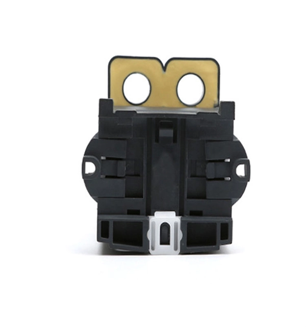
Simply put, a relay is an electromechanical device that allows a high power load to be controlled with a low power circuit. The images below show a cross section of a relay very similar to what is on the RELAYpl.
[PDF]

Traditional electromechanical relays rely on fixed settings that cannot adapt to variable grid conditions. This often results in miscoordination, delayed fault clearing, or unnecessary tripping, compromising reliability. able sources such as wind and solar. These clean energy sources, connected through inverters and flexible transmission systems, are transforming traditional grids based on synchronous generators into more flexibl cant challenges to system stability. Nowhere is that clearer than in the challenge to. Relay protection systems are essential in maintaining the safety and reliability of modern electrical grids. As technology advances and grids become smarter, the tools used to test and maintain these systems, such as the relay test set, are evolving to meet new challenges. This article explores the. By taking a series of countermeasures, the paper explored the influence of new energy connection on traditional relay protection systems in response to the occurrence of the above phenomenon. These countermeasures include protection logic and settings optimization, fast fault detection technology. Abstract—This paper discusses the impact of inverter-based resources (IBRs) in traditional digital protection relays applied in the interconnection transmission line between the IBR and bulk power system. This paper explores the development of relay protection technology in smart grids, analyzing.
[PDF]

This guide describes the general requirements, functional and technical performance requirements, test requirements, labeling and packaging requirements, transportation and storage requirements, supply integrity requirements, and quality assurance requirements for hybrid high-voltage. This guide describes the general requirements, functional and technical performance requirements, test requirements, labeling and packaging requirements, transportation and storage requirements, supply integrity requirements, and quality assurance requirements for hybrid high-voltage. Guide for Technical Requirements for Hybrid High-Voltage Direct Current Transmission Protection and Control Equipment This guide describes the general requirements, functional and technical performance requirements, test requirements, labeling and packaging requirements, transportation and storage. purpose of this white paper is to aid WECC members (Specifier) in specifying and applying relay systems that will provide adequate protection of extra-high voltage (EHV) on 345-kV or higher transmission lines and comply with the NERC Reliability Standards. The recommendations in this white paper.
[PDF]

Fiber optic terminal boxes provide functions such as input, branching and splicing of optical fiber cables. Through the connectors and splicing boxes in the terminal box, optical fibers can be quickly connected and repaired. Serving as a critical connection point, FTB facilitates the termination, splicing, or connection of fibers from various cables to other network devices such as switches, routers, or Optical Network Terminals (ONTs). It aids in splicing, splitting, storing, and managing fibers within the appropriate. The optical fiber terminal box is the terminal joint of an optical cable, one end of which is an optical cable, and the other end is a pigtail, which is equivalent to a device that splits an optical cable into a single optical fiber. A fiber pigtail is a specific hardware connection used for cable termination. It is a small enclosure that can house and protect the fiber optic cables, splices, and connectors. The optical fiber termination box and optical fiber splice box serve distinct purposes and are not interchangeable.
[PDF]

The presence of a strong sealant in the closure helps prevent water and air from entering it. Some splice closures have all cables entering into one end, usually called dome closures or sometimes called a butt closure, while some have cable entries on both ends, sometimes called inline closures. Inline closures are used in applications where two identical cables are spliced and an inline. Fiber splice joint closures are vital but often overlooked. It plays a crucial role in keeping networks running smoothly, even in the harshest conditions. Let's explore what they are, why they matter, and how technological advancements are making them even better. Fiber splice joint closures are. A fiber optic splice closure is a protective enclosure designed to house and protect fiber optic splices and, in some cases, passive optical components. It provides mechanical protection, environmental sealing, and internal fiber management for spliced optical fibers. Fiber optic splice closures have been widely used in various fields such as communication, network systems, CATV, etc. There are. CommScope addresses these challenges with a comprehensive family of fiber splice closures that prioritize essential criteria: reliability, installability, flexibility, and speed of deployment. Whether underground, aerial, or in manholes, splice closures are the first line of defense against environmental threats to your fiber.
[PDF]
A 24-port patch panel is a networking device that allows for the organization and management of incoming and outgoing network connections. It acts as an interface between different devices such as computers, switches, and routers, allowing for easy connectivity and communication. This guide explains how to use a 24-port patch panel to manage copper and fiber cabling in a small LAN, how to choose between different patch panel types, how to design your cabinet layout, and why a patch panel is still irreplaceable in 2026. What is a Patch Panel and Why it Matters in 2026? A. Choosing a 24-port patch panel is crucial for efficiency. Learn how it enhances network capabilities. Typically, patch panels are available in a huge number of port densities from 12. In this article, we will define what a patch panel 24 port is, explain its purpose, and discuss why it is a crucial component in organising network cables. A patch panel 24 port is a device used in network cabling to connect and organise multiple network cables in one central location. It is a. Choose a 24-port patch panel when you care about clean labeling, comfortable “finger room,” and fast moves/adds/changes—especially if technicians touch the rack often and you want straightforward port-to-port mapping (Panel 01–24 ↔ Switch 01–24). Choose based on port density, cabinet space.
[PDF]

They are the bridge between fiber optic cables in the field and the equipment or patch panels that manage them. By combining factory-installed connectors with spliced bare fiber, pigtails ensure that network installers can create fast, reliable, and cost-effective terminations. Fiber pigtails are simple in appearance, yet essential in function. This unique design is the key to seamless integration with a variety of optical devices, ensuring signals traverse with. Executive Summary: A fiber optic pigtail is one of the most commonly specified yet least understood components in structured cabling. Get the wrong connector type, the wrong polish, or skip proper fusion splicing technique—and you're looking at elevated signal loss, increased back reflection, and a. A pigtail fiber indicates a short length of optical fiber cable that has a pigtail connector (for example, SC, FC, ST, LC, etc. ) fitted on one end and the other end undressed (for connection through fusion or splicing) to the main fiber optic cable. This essential function of pigtail fiber is. Fiber optic pigtails are short, single, or multi-strand pieces of optical fiber cables with a connector on one end and exposed fiber on the other end. But what exactly is a pigtail and why do you use it? In this article, we explain why they are important and which pigtail connector you should choose, with a focus on SC and LC pigtails. What is a pigtail? A pigtail is used to.
[PDF]

Beamsplitters are commonly employed in lasers to create different beam paths, achieving this effect by dividing the laser beam into multiple segments and then recombining them. This allows the direction and intensity of the beam to be adjusted with outstanding precision and. Beamsplitters are fundamental components in optical engineering, serving to precisely divide a single input beam of light into two distinct output beams. This division allows for the simultaneous analysis or utilization of the light's properties along two separate paths. It is a crucial part of many optical experimental and measurement systems, such as interferometers, also finding widespread application in fibre optic telecommunications. In its. This article explains how to create a beam splitter cube in Sequential Mode. One of the biggest challenges for modeling such a system is that multiple ray paths cannot be simultaneously traced in Sequential Mode. These versatile tools can split both laser and regular light, depending on the application in question. Beamsplitters are often classified according to their construction: cube or plate. Beam splitter divides a beam of light into two or more separate beams. Beam splitters can be made from different materials and are often coated with thin layers of metal or dielectric materials.
[PDF]
The aluminium alloy joint box are applicable for connection protection of special optical cables,with the functions of direct and branch connection, with the maximum of 6 optical cables, which mainly for overhead rods and towers. Explore top-quality OPGW hardware fittings, setting a new standard for secure and efficient connections in our Pole Line Hardware. The joint box is made of aluminium alloy and has a maximum capacity of 192 fibre splices. A pre-moulded neoprene anti-aging gasket. No. 77, East District, Sixian Industrial Zone, West Ring Road Office, Renqiu City,. An assembling plate trays is placed inside the box. Cable glands and a heavy wall OPGW cables. The anchoring of the joint box to the tower is poles. It features in high mechanical strength, good airtight and anti-corrosive. Having been sealed with sealing ring and silicone, it could be opened, expansed, fixed, and connected repeatedly. It's suitable in aerial. Optical cable junction boxes play a crucial role in connecting and protecting optical fibers, directly influencing the quality and lifespan of optical cable routes. Optical cable splice boxes protect the splicing parts of optical fibers from various hazards, such as water seepage due to adverse.
[PDF]

An elevator data communication system is configured to communicate between a plurality of elevator systems and a datacenter remotely located from the plurality of elevator systems. WAN – Wide area network is similar to a LAN but is not limited to a single location. It can also consist of several LANs which are interconnected. Usually, it is the only way how to contact the outside world and get help when you are trapped in the elevator. But many changes and exciting new challenges are coming in the field of elevator. “THE LONGEST RUNNING PUBLICATION FOR THE VERTICAL TRANSPORTATION INDUSTRY SINCE 1953. ” Open and standard communication protocols are vital for interoperability in building automation and elevators. The OSI seven-layer model frames protocol design but compliance alone does not guarantee. Elevators are essential in most modern buildings, but they need communication systems that meet code requirements. Here's how new features are making compliance easier—and delivering a new revenue stream. More sophisticated and effective communication solutions are needed to manage the increasing. Technical systems are, in general, becoming ever more complex. Electronic systems – usually equipped with tiny embedded microprocessors – are implementing new functions, increasing convenience or improving system safety and reliability.
[PDF]

