
Recommendation ITU-T L. 101 describes characteristics, construction and test methods of optical fibre cables for buried application. 0, in February 2016. The short answer, based on general industry standards and the National Electrical Code (NEC), is that fiber optic cable is typically buried between 24 inches (60 cm) and 30 inches (76 cm) deep. However, simply hitting this depth isn't enough to guarantee your network survives. Factors like the. Underground fiber optic cable installation follows specific standards that govern burial depth, testing methods, installation techniques, and safety requirements. 5 is an article in the National Electrical Code that addresses requirements for underground electrical installations, including minimum cover requirements—the measurement used to determine the distance from the top of an underground cable or raceway to the finished grade. 5. Estimate minimum burial depth (cover) for underground electrical, fiber, and low-voltage cable runs using a practical, code-aware ruleset. Use this page to plan trench depth, compare conduit options, and prepare for inspection conversations. Use this calculator to estimate a minimum burial depth. Recommendation ITU-T L. This depth is generally considered the absolute shallowest for any telecommunications cable that is not placed.
[PDF]
This chapter presents the development of the Energy Internet throughout the history as an evolutionary solution based on modern technological development and needs, with the respect of its architecture, key features, and key concepts, such as energy router, prosumer, and virtual. This chapter presents the development of the Energy Internet throughout the history as an evolutionary solution based on modern technological development and needs, with the respect of its architecture, key features, and key concepts, such as energy router, prosumer, and virtual. Energy Internet, a futuristic evolution of electricity system, is conceptualized as an energy sharing network. The. ITM University Gwalior, India. coordinating and controlling the many parts of a system, whether they are locally located or geographically dispersed. The study wraps up by outlining the most pressing problems that will need to be solved in order to implement an.
[PDF]
The machine is a hand-held free-to-height cable quick-attachment tool with internal components such as controllers that automatically complete all steps of cable tying. It can be widely used in the high-altitude operation in the field of communication engineering and is. Power Source: Rechargeable lithium battery Bundling range: 0-60mm Binding : can binding 1600 times for one time fully charger. Voltage: 12V Battery: 7800 mAh/group, Fully charged, one battery can work more than 1600 times, about 3 kilometers or more Battery installation mode: external and embedded. Delivery time is estimated using our proprietary method which is based on the buyer's proximity to the item location, the shipping service selected, the seller's shipping history, and other factors. Delivery times may vary, especially during peak periods. Buyer pays for return. Buy Newly Designed Second Generation High Altitude Optical Fiber Cable Bundling Machine for Efficient Network Installation at Aliexpress for. Find more 1420, 153713 and 1537 products. Enjoy ✓Free Shipping Worldwide! ✓Limited Time Sale ✓Easy Return. Maximum order quantity: 1 piece Customized logo (+ from /Min.
[PDF]

Bury cables from 12-36 inches (or 30-90 cm) deep. Where plant life, sidewalks, and other utilities already disrupt earth, it's safer to bury at as little as 24 inches or 60 cm, using protective conduits to limit the likelihood of damaged cables by inexperienced maintenance or. Bury cables from 12-36 inches (or 30-90 cm) deep. However, simply hitting this depth isn't enough to guarantee your network survives. Factors like the. Requirements vary based on location, cable type, and local regulations, with depths typically ranging from 18 to 48 inches. Residential areas require depths between 24 and 36 inches for most installations. This protects cables from landscaping activities and minor excavation work. This. The question of how deep to bury fiber optic cable has no single answer, as the required depth changes significantly based on location, environment, and specific application. Industry standards and regulations, such as those often referenced in the National Electrical Code (NEC), establish a. Fiber optic cables are typically buried between 12 and 36 inches (30–90 cm), depending on installation environment, soil conditions, and load requirements. In high-load areas such as roads or backbone routes, burial depth can reach 48 inches (120 cm) or more. This guide provides a comprehensive overview of industry.
[PDF]

Telescopic mast system with advanced vibration-dampening technology to minimize jitter and ensure stable communication and data transmission, even in the most demanding terrain and vehicle movements. Fireco designs and manufactures the most comprehensive line of standard and custom telescopic masts using high quality materials with industry leading engineering and quality testing practices to provide our customers with the world's best mobile masts. Will-Burt's telescopic masts and tower systems provide intelligent. Telescopic mast systems play a critical role in modern field operations—enabling elevation of cameras, antennas, lights, sensors, and communication gear in demanding environments. Whether for surveillance, broadcasting, defense, or emergency response, choosing the right mast system ensures reliable. Floatograph, along with its utility industry partner, Eversource Energy, developed the Rapid Pole® – Temporary Power Pole system to reduce customer downtime, allowing crews to re-energize a circuit in as little as 20 minutes. Floatograph's masts come in height options from 10 to 100 feet, and are. Advanced telescopic mast solutions designed for versatility in the field, providing crucial support for on-the-move (OTM) missions. Erecting the Telescoping Mast is made by simply connecting guys and brackets to the attached unique heavy duty rolled edge guy rings and clamps, extend the sections, insert the locking cotter pins, rotating the tubes to.
[PDF]

Unlike DSL or cable, which use copper wires, fiber optic Internet service relies on optical fiber to transmit data. These fiber optic cables, made of glass or plastic, use light pulses instead of electrical signals, enabling high-speed Internet with low latency and reliable. The process involves a combination of national infrastructure, local engineering, and property-level setup. In this guide, we'll break down the fiber installation process from start to finish and explain key components such as fiber cabinets, flower pods, ducting, and ONT setup. What Is Fiber Optic. Fiber optic internet represents a significant leap forward in broadband technology, offering speeds and reliability far exceeding traditional cable or DSL connections. Check availability first by contacting your internet service provider or visiting their website—fiber now passes over 76 million. The fiber is connected to an Optical Network Terminal (ONT) inside or outside your home. The ONT converts the light from th e fiber into electrical signals that run via an ethernet cable. This fundamental difference is the key to its superior speed, bandwidth, and reliability. The light signals travel at near the speed of light.
[PDF]

The two primary industry-accepted methods for fiber optic cable splicing are fusion splicing and mechanical splicing. The choice between them depends on performance requirements, budget constraints, and the specific application environment. To begin, the standard definition of splicing in optical fiber is joining two fiber optic cables together. Splicing is most commonly used in the field but has application in cable assembly houses. Infield. In this guide, we cover the basics of fiber optic splicing, how to perform splicing using two different methods, and finally some best practices to perform good fiber splicing. What is Fiber Optic Splicing and Why is it Needed? – #1. In this guide, we'll explore what splicing of fiber entails, why it's important, and dive into the key methods and tools. So in essence, fiber optic splicing is a process used to join two separate fiber optic cables together. Through splicing, fiber optic technicians can extend the length of the fiber to make it long enough for use in a required cable run. As. Splicing fiber optic cable is an extremely important phase for making dependable, high-speed communication infrastructures. Termination is the other, more frequent way of linking fibers. Fiber splicing is the preferred way when cable lines are too long for a single length of fiber or when combining two different types of cable.
[PDF]

Will fiber optic cables replace coaxial cables entirely? The short answer is: not entirely. In this article, we'll help you understand where each. Fiber optic cables and coaxial cables have something in common; both of them can provide homes and businesses with tv, phone, and Internet service. Cables. Optical fiber can carry analog RF signals from antenna to receiver with far less loss than coaxial cables. It's not unusual in engineering to find solutions to long-standing problems leveraging apparently unrelated technologies. But these signals have a fatal flaw: when transmitted through traditional copper coaxial cables, they degrade and distort rapidly over distance. It's like shouting into a long metal pipe—the sound that comes out the other. Seamless Radio Frequency Signal Transmission over Optical Networks RF over Fiber (RFoF) technology enables the transmission of radio frequency (RF) signals over optical fiber instead of traditional coaxial cables. This method combines the advantages of fiber optics—such as low signal attenuation.
[PDF]

Mainly 9steps: Step 1: cut cable with cutting machines in lengths Step 2: put the connector spare parts on the cable Step 3: Strip cable jacket, coating till bare fiber, and make all parts in ready Step 4: Insert fiber into ferrule, glue dispenser and heat oven Step 5:. Mainly 9steps: Step 1: cut cable with cutting machines in lengths Step 2: put the connector spare parts on the cable Step 3: Strip cable jacket, coating till bare fiber, and make all parts in ready Step 4: Insert fiber into ferrule, glue dispenser and heat oven Step 5:. Learn how to make a fiber optic patch cord step by step, from preparation to testing, for reliable high-performance connections. Most guides on making fiber optic patch cord 1 s feel incomplete. They often focus on the final assembly steps, leaving the foundational stages a mystery. From cable cutting to connector assembly and testing, you will gain valuable insights into the production of. Fiber optic patch cords and Pigtails are very important passive fiber optic components in fiber optic networks. Use the fiber optic cleaver to cut the. This document describes the installation and use of the mode-conditioning patch cords listed in Table 1. A mode-conditioning patch cord is shown in Figure 1 IEEE 802. 3z-compliant optical fiber assembly consisting of a single-mode fiber permanently coupled off-center to a 62. 5-micron multimode.
[PDF]

This Report Provides In-Depth Analysis of the U. Fiber-Optic Cable Market Report Prepared by P&S Intelligence, Segmented by Type (Single-mode, Multi-mode, Plastic Optical Fibre), Cable Type (Loose Tube, Tight-Buffered, Ribbon, Armored, Simplex & Duplex Cable), Fiber Type. This Report Provides In-Depth Analysis of the U. The growth of market is attributed to factors such as proliferation of data centres and increasing deployment of 5G network. Increased broadband. The fiber optics industry is projected to reach USD 6. 8 billion by 2029 from USD 3. 4% from 2024 to 2029. Rapid expansion of data centers, cloud services, and 5G infrastructure is driving strong adoption of fiber optic solutions. Rising internet penetration and. Fiber optic cable market has emerged as vital part of the worldwide telecommunications and data transmission system. The fibre optic cables that carry the data by the use of light signals have a much greater advantage over traditional copper cables because they have a higher bandwidth, faster. Fiber optic cables are high velocity information transmission mediums that utilize slight strands of glass or plastic filaments to send data as light signals over significant distances.
[PDF]
There are hybrid optical and electrical cables that are used in wireless outdoor Fiber To The Antenna (FTTA) applications. In these cables, the optical fibers carry information, and the electrical conductors are used to transmit power. These cables can be placed in several environments to serve antennas mounted on poles, towers, and other structures. According to Telcordia GR-3173, Gener. OverviewA fiber-optic cable, also known as an optical-fiber cable, is an assembly similar to an but containing one or more that are used to carry light. The optical fiber elements are typically individually. Optical fiber consists of a and a layer, selected for due to the difference in the between the two. In practical fibers, the cladding is usually coated wit. In September 2012, NTT Japan demonstrated a single fiber cable that was able to transfer 1 per second (10 bits/s) over a distance of 50 kilometers. Although larger cables are available, the highest stra.
[PDF]

Traditional turbidity monitoring methods involve the manual collection of water samples at set locations and times followed by laboratory analysis, which are labor intensive and time consuming. Fiber-optic measurement permits real-time, in situ turbidity monitoring. But the current technology is. This paper presents the development of an optical fiber sensor system for multiparametric assessment of temperature and turbidity in liquid samples. The sensors are based on the combination between fiber Bragg gratings (FBGs), intensity variation and surface plasmon resonance (SPR) sensors. Electrical, Electronic and Communication Engineering Dept. ; bFiber Photonics Department, UMR CNRS/University of Limoges 7252, 123 Avenue Albert Thomas, 87060 Limoges cedex, France; c“Grupo de Ingeniería fotónica”, Avenida Los Castr s. Turbidity is caused by the presence of suspended particles, organic matter, and chemicals, and is widely measured in natural resources, irrigation water, the food and beverage industry, and drinking water [1,2,3]. As an important water quality parameter, turbidity not only indicates the efficiency. Create a new folder below. Sensors were designed in two versions: for examination of liquid samples and for monitoring of transparency in the flow of liquids ('on-line'.
[PDF]
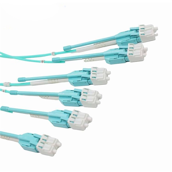
The fiber connector types, sometimes referred to as terminations, link fiber optic cables together through terminals, switches, adapters, and patch panels, by bridging the gap between their internal glass fi.
[PDF]


