This chapter presents the development of the Energy Internet throughout the history as an evolutionary solution based on modern technological development and needs, with the respect of its architecture, key features, and key concepts, such as energy router, prosumer, and virtual. This chapter presents the development of the Energy Internet throughout the history as an evolutionary solution based on modern technological development and needs, with the respect of its architecture, key features, and key concepts, such as energy router, prosumer, and virtual. Energy Internet, a futuristic evolution of electricity system, is conceptualized as an energy sharing network. The. ITM University Gwalior, India. coordinating and controlling the many parts of a system, whether they are locally located or geographically dispersed. The study wraps up by outlining the most pressing problems that will need to be solved in order to implement an.
[PDF]

Urban Areas: 25–40m spacing (concrete poles, 10–12m height)., steel lattice structures). Factors: Cable weight (kg/km) Ice loading (up to 50mm. The Fiber Optic Association, Inc. (FOA) was founded in 1995 to help develop the workforce to build the fiber optic networks to support a rapid expansion in communications and the Internet. The charter of the FOA was to promote professionalism in fiber optics through education, certification, and. to n utral comm. cable R. FO-CS JOINT USE CLIMBING SPACE REQUIREMENTS 51. APPENDIX A - COVER SHEET / TOC 52. RUS DRAWING #PM12 58. CHECK. d suppliers of electrical construction services. They define a minimum baseline of quality and workmanshi for installing electrical products and systems. NEIS® are intended to be referenced in contrac documents for electrical construction ation or liability to users of this publication. Choose the type of pole The basic pole height is 7m and the tip diameter is 150mm. In case of special sections, crossing obstacles or roads or railways, the pole height of 8m, 9m, etc. can be selected. Cables 300 V or less need to be a minimum two feet over the street light. Climbing Space is an unobstructed, vertical space along the side or corner of the pole. In gen-eral, it consists of an imaginary box, 30-inches square, extending at least 40 inches above the highest communications cable or.
[PDF]
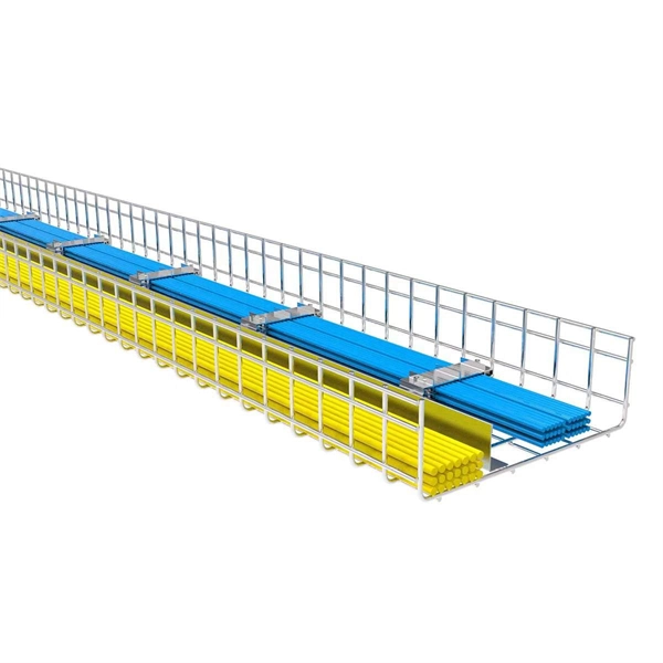
Standard splice plates can often provide a safe electrical path if they are UL Classified and bolted tight. However, you must use copper bonding jumpers if the tray is painted or has expansion joints for movement. A. The intent of this article is to review grounding practices for cable tray wiring systems. The Equipment Grounding Conductor is the electrical circuit's safety conductor. When designing a cable tray. Snap Track requires only single bonding jumper. Installation Guideline: Scroll to bottom of page to view All Bonding Jumpers Cut Sheets A bonding jumper is required to be installed with adjustable splices and expansion splices. If an EGC cable is installed in or on a cable tray, it should be bonded to each or alternate cable tray sections via grounding clamps (this is not required by the NEC® but it is a desirable practice). In addition to providing an. Do I have to use a bonding jumper at each cable tray splice point that is bolted tightly together? I currently have 3 runs of 24 tray about 80ft long. we have one expansion plate section per run in which I plan on using a bonding jumper at, I am curious about all other points You aren't even. Wire mesh cable trays are widely used in commercial offices, industrial facilities, data centers, and smart building infrastructure because they provide unmatched flexibility, excellent airflow, and fast, adaptable installation. Their open-grid design makes it easy to route, add, or modify cabling.
[PDF]
This document outlines the key requirements for cable tray layout, installation, and fireproofing in industrial and commercial environments. Route Planning and Layout Principles. Provides technical requirements concerning the construction, testing, and performance of metal cable tray systems. It is the first joint effort of NEMA and CSA International to put in one place standards for metal trays per both NEMA and CSA methods. Addresses shipping. Method Statement installation of Cable Trays and Ladders - Planning Engineer FZE. Whether you're designing a new. Below is the detailed cable tray installation method statement not only for cable tray but also applicable for GI ladder and trunking for indoor and outdoor applications and in service rooms like pump rooms, electrical rooms and plant rooms etc. All materials intended for cable tray, ladder and. Cable tray installation must comply with specific technical standards to ensure electrical safety, system reliability, and long-term maintainability. The mechanical and electrical characteristics, tests, certifications, overall quality management, recommendations mentioned in this technical guide only apply to our own cable management ranges and cannot under any circumstances be transpos regulations which.
[PDF]

This guide will walk you through each stage of the compliance and permitting process for outdoor kitchens, highlighting common pitfalls, must-follow codes, and tips for smooth project approval. Barbecue grills shoved into a corner of the deck have evolved into full-blown outdoor kitchens. As a “code guy,” I should point out that the International Residential Code (IRC) has a few things to say about kitchens, and it doesn't care if the kitchen is inside or outside the house. The gas pipe. Building your dream outdoor kitchen is an exciting project, but it's essential to understand the outdoor kitchen code requirements in your area. These codes vary by location and typically cover aspects like electrical, plumbing, and construction standards. Building an outdoor kitchen can transform your backyard into a functional and attractive space for cooking and entertaining. Who can resist the aroma of food cooking. Building an outdoor kitchen is not as simple as setting up a barbecue and a countertop—there are legal, safety, and logistical hurdles that, if ignored, can lead to costly fines, project delays, forced teardown, or even safety hazards down the line. Many homeowners are surprised to discover that. Installing an outdoor kitchen is one of the most desirable upgrades for homeowners who want to make the most of their backyard.
[PDF]

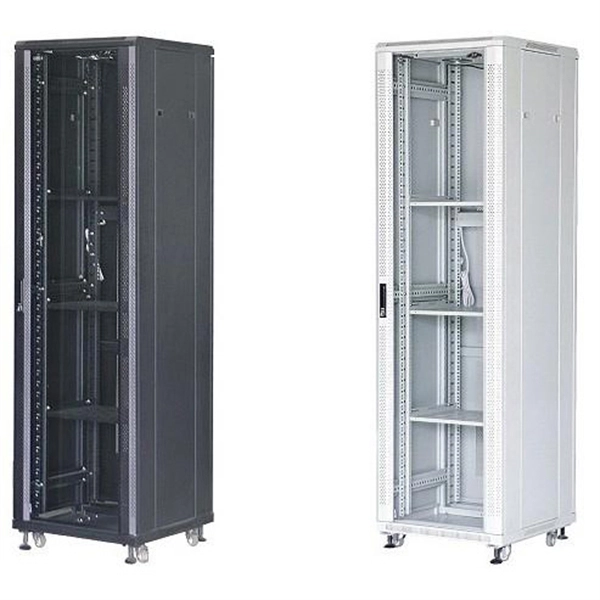
All meter and service equipment installations shall comply with the service requirements of CRA-ES and with rules and regulations of the inspection authorities having jurisdiction. All meter sockets and enclosures shall be listed and approved by a recognized testing lab. If any question arises for. Added dual meter for ethernet over IP without breakout block. Updated standard includes newer design that no longer requires breakout block and cellular data update. Note for window clearance added on page 6. Current. This informational booklet is issued by American Electric Power Company for the guidance of Customers, Engineers, Architects, Contractors and other interested parties planning electrical installations for residential buildings and small commercial establishments. The information and recommendations. Submit Service Request forms describing the proposed electrical installation and expected loads. Include the existing service designation and meter location for rewires or upgrades to the existing service. For residential. The DTE Electric Planner will determine the location of the building service and the meter equipment. Choose the right box based on environment (indoor/outdoor), load capacity, and durability. Check for proper IP/NEMA ratings and material quality. Ensure safe placement: install in.
[PDF]

This document provides specifications for various distribution boxes including dimensions, mounting sizes, and number of ways. It stipulates requirements for enclosure materials, installation dimensions, the mandatory "one equipment, one switch, one RCD" rule, mechanical structure, earthing systems. RB21 is a portable, safe, economic and easy to use pre-wired low voltage ready board with 2 (Two) sockets, 1 (One) lighting lamp and protection area. It has 4 (Four) mounting lugs suitable for wall installation and additional knockout for future use. It is suitable for residential (small holding. The World Bank is financing the National Electrification Analysis (NEA) on behalf of the GoA for which NRECA International (NRECA) was contracted in September 2019. The NEA project is designed to perform a geospatial evaluation of electrification access options to achieve GoA access goals by. This guide walks you through everything about electrical enclosure box sizes — from measurement standards and IP ratings to sizing formulas and common pitfalls. Before talking numbers, let's clarify what “size” really means. Dimensions included are length, width. IEC 62262 IK10.
[PDF]
Provides technical requirements concerning the construction, testing, and performance of metal cable tray systems. It is the first joint effort of NEMA and CSA International to put in one place standards for metal trays per both NEMA and CSA methods. Addresses shipping. association representing the major electrical equipment manufac-turers in the U. The Cable Tray ng standards, performance standards, test standards and application in this document have been tested extens ompetent professional en completely installed, without damage either to conductors or. Cable tray (or cable ladder) systems are a popular alternative to electrical conduit systems, as they have an outstanding record for dependable service, design flexibility and cost savings in commercial and industrial applications. A properly designed and installed cable tray system will provide. us-trations without notice. All illustrations, descriptions and technical information included in this document are provided as indications and can cable trays are equivalent. The mechanical and electrical characteristics, tests, certifications, overall quality management, recommendations mentioned. Not all cable trays are equivalent. The content is written to be SEO-friendly and compatible with Yoast SEO for WordPress. Introduction and.
[PDF]

Protective relays are essential devices used in electrical power systems to detect faults and abnormal conditions, initiating corrective actions to prevent equipment damage and ensure system stability. These relays play a crucial role in the protection of transformers, generators, transmission. A protective relay is an intelligent device that senses abnormal electrical conditions, such as overcurrent, under-voltage, or frequency deviations. It initiates the operation of circuit breakers to isolate the affected section. This prevents damage to equipment, reduces downtime, and safeguards. Protective relays are critical components in power systems, providing essential protection for various elements such as generator sets, outgoing feeder and load networks, and incoming utility sources. It functions as a watchdog by constantly surveying multiple system components including voltage, current, frequency, and phase angle. It. Protective relays and devices have been developed over 100 years ago to provide “lastline”of defense for the electrical systems. They are intended to quickly identify a fault and isolate it so the balance of the system continue to run under normal conditions. The selection and applications of.
[PDF]

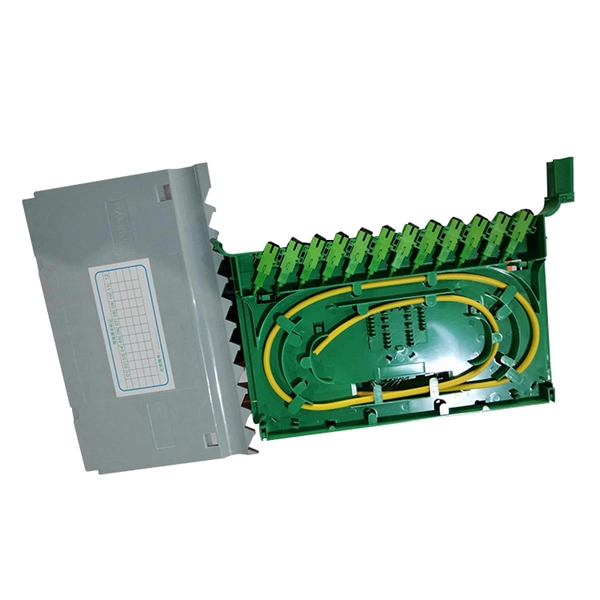
Splice Diagrams or Matrices capture an electric or optical network inside a location – documenting cables, ported equipment, and connections. Splices are fiber-to-fiber, port-to-fiber and port-to-port. Fiber optic cable splicing involves joining two fiber optic cables together. Another method of connecting optical fibers is termination or connectorization, which consists of processing the end of a fiber optic bundle so that it can be connected to other fibers or devices through fiber optic. In this guide, we cover the basics of fiber optic splicing, how to perform splicing using two different methods, and finally some best practices to perform good fiber splicing. Ensure Your Splicing Tools are Clean – #2. Use and Maintain Your. What to show on a network diagram? Fiber optic network diagrams represent the architecture and connectivity of fiber optic systems, and their design philosophy integrates technical, functional, and conceptual aspects. The diagrams abstract complex details of fiber optic systems to make them. This Geoschematics drawing remains easy to read despite containing more than 2000 fibers and 500 splices. All students and instructors must wear safety glasses in this lab. It is copyrighted by the FOA and may not be distributed without FOA permission. This VHO covers similar material to the videos on YouTube. The lab manual has several.
[PDF]

Recommendation ITU-T L. 163 describes criteria for the installation of optical fibre cables defined in Recommendation ITU-T L. 110 in remote areas with lack of usual infrastructure for installation including the procedures of cable-route planning, cable selection, cable-installation. The Fiber Optic Association, Inc. (FOA) was founded in 1995 to help develop the workforce to build the fiber optic networks to support a rapid expansion in communications and the Internet. They define a minimum baseline of quality and workmanshi for installing electrical products and systems. NEIS® are intended to be referenced in contrac documents for electrical construction ation or liability to users of this publication. Existence. This section covers Agency requirements for fiber optic service entrance cables intended for aerial installation either by attachment to a support strand or by an integrated self-supporting arrangement, for underground application by placement in a duct, or for buried installations by trenching. National Electrical Installation StandardsTM are designed to improve communication among speci-fiers, purchasers, and suppliers of electrical construc-tion services. This Standard may also apply to the Jet Propulsion Laboratory other contractors, grant recipients, or parties to agreements PR 8735. 2, Hardware Quality Assurance Program Requirements for Programs and Projects.
[PDF]
