Plug the control cable of Fan 1 to the Quick-Connect box. Use cable ties to mount the control wiring to the wall panel ensuring it is taut, secure, and supported. The white wire from the fixture is connected directly to the source neutral wire, either at the fixture box or through a splice at the switch box. In some household circuits, the white wire may also be. Ceiling fan installation is electrically simple (15A circuit, 14 AWG) but the critical requirement is a fan-rated electrical box per NEC 314. A standard light fixture box cannot support the weight and vibration of a ceiling fan. Route and fasten harness to the bulkhead wall after it has been plugged into the. Check each product page for other buying options. Price and other details may vary based on product size and color. Shop products from small business brands sold in Amazon's store. Learn more. A ceiling fan is a dynamic appliance requiring specialized support beyond what a standard junction box provides. Installation focuses on replacing the general-purpose box with a fan-rated version secured directly to the ceiling framework. New Work Fan Rated Electrical Ceiling Box with Captive Nails (B520A-CFB) Carlon 1-Gang 20 cu.
[PDF]

A lighting control module operates as the central controller for a lighting system. It receives input from switches, apps, or sensors and regulates electrical flow to connected lights. Depending on the setup, it adjusts brightness, color temperature, or full lighting scenes. It acts as a bridge between your physical lighting fixtures and the smart systems that manage them. Instead of relying solely on traditional wall switches, you can control your lights via remotes, mobile or web apps. A lighting control module is an essential component in a lighting control system that manages how lights are powered, dimmed, or switched on and off. Think of it as the “brain” that receives commands—either from a manual switch, a sensor, or a building automation system—and translates them into. A lighting control module is a smart device that manages lighting circuits, adjusting brightness, automating schedules, and responding to sensors. It enhances comfort, efficiency, and ambience in homes and commercial spaces. Explore the multifaceted benefits and applications of lighting control modules, from home automation to industrial. These modules are designed to communicate with various sensors, switches, and control panels, making lighting adaptable to different environments and user preferences. It enables precise management of lighting systems, allowing for adjustments in brightness, color, timing, and even integration with other smart devices. This innovation.
[PDF]

Therm-X is a specialist in thermal systems, temperature sensors, heaters, thermocouples, controllers and resistance temperature detectors (RTDs) for renewable technologies. We have designed and co-developed temperature sensitive process equipment for solar, fuel cells, and other. In this comprehensive guide, you'll discover how temperature monitoring systems optimize photovoltaic power plant performance. We. Our Temperature Sensors ensure reliable and accurate temperature readings in all conditions. Constructed with premium materials and calibrated for precision, these sensors are designed for durability and stability, providing dependable performance over time. This TI Design addresses the key need of a highly cost-optimized monitoring and communication subsystem for solar module level power electronics (MLPE). This design. In addition to the standard line, ACS is able to offer customized solutions thanks to its more than 60 years of experience in designing customized environmental simulation chambers, its technical know-how and the close attention given to the requests of all our customers. Example of a chamber. We have designed and built simple custom temperature control solutions from single zone 150W panels up to large +850kW multi-zone/multi-circuit panels with a full HMI and plant-wide DCS integration. Below are some custom features we can add to your panel. Contact us to discuss your specific.
[PDF]

These numerical codes, ranging from 1 to 99, uniquely identify the functions of protective relays, associated devices, and control equipment in electrical power systems. In electric power systems and industrial automation, ANSI Device Numbers can be used to identify equipment and devices in a system such as relays, circuit breakers, or instruments. The device numbers are enumerated in ANSI / IEEE Standard C37. 2 Standard for Electrical Power System Device Function. According to the ANSI/IEEE standards, device function numbers are crucial identifiers in power system protection and control engineering. ANSI IEEE Standard Device Numbers are below: (the more commonly used ones are in bold) 86T is a Lockout Relay for a. The widely used United Sates standard ANSI/IEEE C37. Even in those parts of the world where IEC standards are predominate, the use of ANSI numbering. For power grid systems, ANSI and IEEE functional number codes dictate the use and restrictions of both the devices themselves, as well as the functions of those devices within the scope of a circuit. These devices include switches, disconnects, circuit breakers, generators, and motors. Instead of verbal descriptions, we use numbers to describe the functions of a relay. Why use numbers instead of words? Efficiency.
[PDF]

The IEEE standard for protection relays refers to a collection of guidelines developed by the Institute of Electrical and Electronics Engineers. These standards define the performance, accuracy, reliability, and testing requirements of protective relays used in electrical systems. Relay systems protect high-voltage equipment and transmission lines to ensure safe, stable systems. Although failure of a protective relay system may have severe local or regional impacts, most protective relay systems are not required to operate to prove they are in working order. Many of the protective relay systems are seldom called upon to work and have little means of proving they. The testing and verification of relay protection devices can be divided into four groups: Type tests are needed to prove that a protection relay meets the claimed specification and follows all relevant standards. Since the basic function of a protection relay is to correctly function under abnormal. Protective relays are decision-making elements in the protection scheme for electrical power systems. A strong test and maintenance program will keep protective relays in a high state of readiness and help utilities avoid equipment damage and prolonged downtime. This guide provides recommended. This utility standard establishes the requirements for testing and maintaining protection systems, automatic reclosing, and sudden pressure relaying.
[PDF]

What is a Full Wave Rectification? Full wave rectifications are a specific type of rectification that transforms the entire AC signal cycle into a pulsing DC signal, one half at a time. Full-wave rectification converts alternating current to DC using numerous diodes. The full wave rectifier converts both halves of each waveform cycle into pulsating DC signal using four rectification diodes. In the previous power diodes tutorial we discussed ways of reducing the ripple or voltage variations on a direct DC voltage by connecting smoothing capacitors across the. Full Wave Rectifier Definition: A full wave rectifier is defined as a device that converts both halves of an AC waveform into a continuous DC signal. Circuit Diagram: The circuit diagrams for both centre-tapped and bridge rectifiers show how diodes are used to ensure the conversion of AC to DC. For the conversion of AC voltage into DC voltage it uses two different types of circuit configurations i. Center Tapped Full Wave Rectifier and Full Wave Bridge Rectifier. Output Voltage: Produces a pulsating DC output with twice the frequency of the. The process of converting the AC current into DC current is called rectification. Rectifiers are generally classified into two types: half wave.
[PDF]
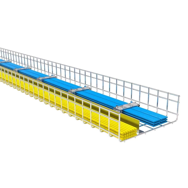
Standard splice plates can often provide a safe electrical path if they are UL Classified and bolted tight. However, you must use copper bonding jumpers if the tray is painted or has expansion joints for movement. A. The intent of this article is to review grounding practices for cable tray wiring systems. The Equipment Grounding Conductor is the electrical circuit's safety conductor. When designing a cable tray. Snap Track requires only single bonding jumper. Installation Guideline: Scroll to bottom of page to view All Bonding Jumpers Cut Sheets A bonding jumper is required to be installed with adjustable splices and expansion splices. If an EGC cable is installed in or on a cable tray, it should be bonded to each or alternate cable tray sections via grounding clamps (this is not required by the NEC® but it is a desirable practice). In addition to providing an. Do I have to use a bonding jumper at each cable tray splice point that is bolted tightly together? I currently have 3 runs of 24 tray about 80ft long. we have one expansion plate section per run in which I plan on using a bonding jumper at, I am curious about all other points You aren't even. Wire mesh cable trays are widely used in commercial offices, industrial facilities, data centers, and smart building infrastructure because they provide unmatched flexibility, excellent airflow, and fast, adaptable installation. Their open-grid design makes it easy to route, add, or modify cabling.
[PDF]
This document outlines the key requirements for cable tray layout, installation, and fireproofing in industrial and commercial environments. Route Planning and Layout Principles. Provides technical requirements concerning the construction, testing, and performance of metal cable tray systems. It is the first joint effort of NEMA and CSA International to put in one place standards for metal trays per both NEMA and CSA methods. Addresses shipping. Method Statement installation of Cable Trays and Ladders - Planning Engineer FZE. Whether you're designing a new. Below is the detailed cable tray installation method statement not only for cable tray but also applicable for GI ladder and trunking for indoor and outdoor applications and in service rooms like pump rooms, electrical rooms and plant rooms etc. All materials intended for cable tray, ladder and. Cable tray installation must comply with specific technical standards to ensure electrical safety, system reliability, and long-term maintainability. The mechanical and electrical characteristics, tests, certifications, overall quality management, recommendations mentioned in this technical guide only apply to our own cable management ranges and cannot under any circumstances be transpos regulations which.
[PDF]
Learn about the market conditions, opportunities, regulations, and business conditions in paraguay, prepared by at U. Embassies worldwide by Commerce Department, State Department and other U. agencies' professionals The standards regime in Paraguay includes obligatory and voluntary standards. The Group's environmental commitment is centred on 3 guiding lines: taking on board environmental management in the running of its industrial sites, reducing the environmental impact of its products by eco-design, providing environmentally friendly solutions that contribute to energy savings. Type. REV.
[PDF]

Provides technical requirements concerning the construction, testing, and performance of metal cable tray systems. It is the first joint effort of NEMA and CSA International to put in one place standards for metal trays per both NEMA and CSA methods. Addresses shipping. Cable trays play a vital role in supporting electrical cables and wires in commercial, industrial, and utility installations. For proper installation, design, and maintenance, adherence to international standards is essential. One of the most recognized frameworks globally is the IEC standard for. association representing the major electrical equipment manufac-turers in the U. The Cable Tray ng standards, performance standards, test standards and application in this document have been tested extens ompetent professional en completely installed, without damage either to conductors or. CABLE TRAYS THE GLOBAL SPECIALISTIN ELECTRICAL AND DIGITAL BUILDING INFRASTRUCTURES TECHNICAL GUIDE Not all cable trays are equivalent. The mechanical and electrical characteristics, tests, certifications, overall quality management, recommendations mentioned in this technical guide only apply to. Not all cable trays are equivalent. For those of you that have experience working with cable tray systems, you have probably noticed the high-level of influence NEMA has in guiding cable tray management projects.
[PDF]
Distance relays, also known as impedance relay, differ in principle from other forms of protection in that their performance is not governed by the magnitude of the current or voltage in the protected circuit but rather on the ratio of these two quantities.OverviewIn, a protective relay is a device designed to trip a when a is detected. The first protective relays were electromagnetic devices, relying on coils operating on moving par. Electromechanical protective relays operate by either, or. Unlike switching type electromechanical with fixed and usually ill-defined operating voltage thresholds. Electromechanical relays can be classified into several different types as follows: "Armature"-type relays have a pivoted lever supported on a hinge or knife-edge pivot, which carries a moving contact. These relays may.
[PDF]

The K factor (or zero-sequence compensation factor) adjusts the measured impedance for the phase-to-ground fault loop by accounting for the contribution of zero-sequence currents. This compensation is critical because zero-sequence current introduces an offset in the fault impedance. The protection and control devices in electrical equipment can be referred to by numbers, with appropriate suffix letters when necessary, according to the functions they perform. These numbers are based on a system that is adopted by a standard for automatic switchgear by Institute of Electrical. The following Terms are used in protective relaying: 1. Fault Clearing Time 5. Drop Out or Reset value 8. Sealing Relay or holding Relay 10. Time-graded protection is implemented using overcurrent relays with either definite time characteristic or inverse time characteristic. The operating time of definite time relays does not depend on the magnitude of the fault cur-rent, while the operating time of inverse time relays is shorter the. Displaying title 47, up to date as of 5/06/2026. Title 47 was last amended 4/30/2026. There have been changes in the last two weeks to Part 90. Without proper. Also principles of various protective relays and schemes including special protection schemes like differential, restricted, directional and distance relays are explained with sketches. The norms of protection of generators, transformers, lines and capacitor banks are also given. The procedures of.
[PDF]
Get Latest Price from the seller Ganesh Electrical - Offering Sifang Relay at Rs 145000 in Gadag, Karnataka. Get Protective Relays at lowest price | ID: 2853527303391. CSC-211 Multifunction Protection IED is selective, reliable and high speed protection IED with rich functions to cover following applications: 1) Protection, bay control unit, MU (Merging Unit), and SCU (Smart control Unit) in one IED; 2) Work as feeder or capacitor bank protection IED; 3) Work as. Copyright © 2020,SIFANG All Right Reserved. Protection relays detect abnormal operating conditions in an industrial system and may trigger an alert or isolate the offending device from the system. The devices can be used for line protection in networks that are grounded, low-resistance grounded, ungrounded, or of a compensated neutral point structure. It is able to supervise. Sifang Relay Install at existing Switch Gear.
[PDF]